| ||||||
| App. F: Providing Improved Ventalation and Light |
Means for Providing Improved Natural Ventilation and Daylight to a Shelter with an Emergency Exit
THE NEED
Survivors in areas of heavy fallout can greatly reduce the radiation doses that they will receive, and thus decrease their risks of contracting cancer, if they sleep and spend many of their non-outdoor-working hours inside good shelters during the first several months after an attack. (See Minimizing Excess Radiogenic Cancer Deaths After a Nuclear Attack, by Kathy S. Gant and Conrad V. Chester, Health Physics, September 1981.)
A permanent family shelter can serve quite well for months as a post-attack temporary home if it is designed to provide adequate natural ventilation most of the time, to have adequate and easy forced ventilation by a KAP when forced ventilation is needed, and to have daylight illumination, A shelter dependent on ventilation laboriously pumped through pipes and on artificial lights even during daytime is much less practical for use as a post-attack home.
The following instructions should enable a family having an earth-covered shelter with an emergency exit to make it much more livable for months-long occupancy. The means described below for providing improved ventilation and daylight illumination also will supply guidance to survivors who will build shelters post-attack to minimize continuing radiation exposures, especially to children and pregnant women,
BUILDING AND USING A MULTI-PURPOSE EMERGENCY EXIT HOUSING
Build a multi-use emergency exit housing of the design pictured in Fig. F,1 and detailed in Fig. F.2, Size your exit housing to fit snugly over the top of your completed vertical exit shaft. This exit housing is made of 3/4-inch exterior plywood, four 2 x 2 x 36-inch boards, and four 16 x 16-inch window panes of 1/8-inch Plexiglas. Plated screws and waterproof adhesives are used to assure sturdiness and durability.
Fig. F.1, Multi-Use Emergency Exit Housing Installed Over the Square Emergency Exit Described by Figs. 17,1, 17.2, and 17.3. (Photograph) 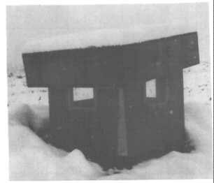
The adjustable top of this exit housing measures 4 x 4 x 1 feet, and can be tilted to make different sized ventilation openings in any of four directions. The top also can be raised straight up to make various sized openings all the way around, or it can be completely closed - as explained by Fig. F.2 and the following descriptions of its uses.
Book Page: 274
Fig. F.2. Plan and Side View of Multi- Purpose Emergency Exit Housing, on a Square Emergency Exit with 34 x 34-Inch Cross- Sectional Outside Dimensions. (Diagram) 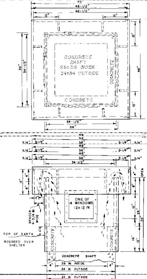
Fig. F.3. The Top and Four Walls of the Multi-Purpose Emergency Exit Housing, Nested Together to Save Storage Space. (Photograph) 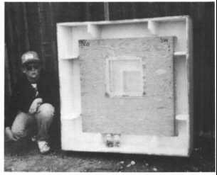
In Figs. F.2 and F.3, note the eight beveled plywood guides, two on the inside of each side of the top. These guides are needed so that the top can be tilted in the position desired, merely by using a stick to raise it from below. To hold the top in a tilted or raised position, spacer boards are placed between the raised top and the upper edges of a wall or walls, as illustrated by Fig. F.4.
Fig. F.4. View from Below the Exit, Looking Up the Multi-Purpose Emergency Exit Housing. The top is shown supported in a tilted position by two 6-inch-wide boards placed between a wall and the top. (Photograph) 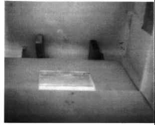
The illustrated housing over a vertical exit provides:
* A means to regulate shelter ventilation, and to increase natural ventilation when the wind is blowing. If, for example, the shelter's opened exit is to the north of its opened entry and a north wind is blowing, shelter airflow will blow in through the exit and out through the entry. This natural ventilating airflow, often inadequate, is increased if the adjustable top of the exit housing is not simply raised 6 inches on all four sides, but is tilted as shown in Fig. F.1, with its south side closed and its north side tilted up 6 inches to provide a 6 x 26-inch ventilation opening between the upper edge of the entry housing's north wall and its top. Then a north wind striking the north wall produces increased air pressure over and above this wall, forcing more air into the exit and on through the shelter. In contrast, if a south wind is blowing, natural airflow will go in through the shelter's entry and out through its exit. And if the adjustable top still is tilted open to the north as illustrated, then reduced air pressure over and above the downwind north wall will "suck" an increased airflow out of the exit and through the shelter.
The measured increases in airflows through a small shelter resulting from the top of this exit housing being tilted were only 40-50 cfm when an 8-10 mph breeze was blowing. These rather small increases in airflow, however, often would make it unnecessary to supply forced ventilation to a family shelter by intermittently operating a KAP.
* Exclusion of rain, snow, and larger dust and fallout particles. The four 12 x 48-inch vertical sides of the adjustable top overhang the exit housing's walls by 6 to 12 inches. Thus the top serves as a large ventilation hood over the exit, preventing rain, snow, and larger dust and fallout particles from entering while ventilation is continuing. (To prevent entry of flies and mosquitoes, an insect screen panel, made to fit over the bottom of the emergency exit, should be kept stored in the shelter until needed. A screen door for the inner entry doorway also should be stored. Remember that installing screens greatly reduces natural ventilation airflows.)
* A reliable source of daylight. The four 12 x 12-inch' windows of this exit housing let enough daylight into the exit shaft, that is painted white, to permit a person on the shelter floor below to read, even for several minutes after sunset. See Fig. F.4.
* A way to observe what is going on all around the shelter, without having to go outside, and with lessened exposure to fallout radiation.
* Quick installation post-attack, after fallout decays sufficiently. In an installation test, dirt was dug away to expose the upper 12 inches of the emergency exit shaft. Then in just 8 minutes the author and a boy carried the 5 parts of this exit housing 80 feet, positioned its four walls around the already exposed upper 12 inches of the reinforced concrete emergency exit, nailed its walls together, and placed its adjustable top in the tilted position pictured in Fig. F.1.
BUILDING AND USING AN ENTRYWAY COVER THAT PROVIDES A LARGE, PROTECTED VENTILATION OPENING
Build a shelter entryway cover that keeps out rain, snow, and the bigger dust and fallout particles while providing a large, protected ventilation opening both for natural ventilation and for easy forced ventilation by a KAP when needed.
Book Page: 275
For an example of one type of entryway cover, see Fig. F.5. This photo shows a 4-piece cover, that two men in a little less than 5 minutes carried out of this shelter and installed over the 4 x 6-foot opening above the shelter's opened stairway doors.
Fig. F.5. A Quickly Installable, 4-Piece Entryway Cover That Provides Easy Access and a Large, Protected Ventilation Opening. 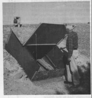
This cover is made of 4 pieces of 1/4-inch chipboard, each 5 feet wide, and short lengths of nailed-on 1 x 2-inch boards. These 4 pieces can be tied quickly with their attached nylon cords to inner parts of the two 2 x 6-foot steel entryway doors, which are pictured in their opened, upright positions.
The lowermost of the 4 chipboard pieces has a groove near each end. The grooves are each made of 2 nailed-on lengths of 1 x 2 lumber spaced apart to fit the lower ends of the doors and hold them in their upright positions 4 feet apart. The upper edge of this lowermost piece is 8 inches below the lower raised corners of the doors, so that an 8 x 48-inch ventilation opening is assured when the lower of the two large covering pieces (pictured being held open) rests on the doors. (This step-over piece of chipboard illustrates a way to reduce the quantity of larger fallout particles that will be blown into many types of shelters, because most sandlike particles and coarse dust are blown along close to the ground. They are not blown upward and over a vertical obstruction by most winds. If an entryway has an inner, ordinary doorway, even more fallout particles can be kept out of the shelter room if an 18 x 18-inch ventilation hole is cut in the door near its top.
Book Page: 276
Then air entering the shelter room will have to rise at least 4 feet above the entryway floor, and most of the larger fallout particles will be deposited on the entryway floor.)
The chipboard piece attached to the upper ends of the doors also has two 1 x 2 boards nailed near each end, forming grooves into which the upper ends of the doors fit. The doors are thus held in their upright positions and rain, etc. is kept from falling or being blown through the upper end into the entryway.
The uppermost of the two large covering pieces of chipboard (or exterior plywood) rests on the opened doors and is kept from slipping down by a 1 x 2-inch board nailed 4 inches from its upper end. This small board "hooks" over the upper edge of the piece of chipboard (or plywood) attached to the upper ends of the steel doors. (See the drawing on the side of this column.) This large piece of chipboard is securely tied to the doors.
To keep the two large pieces from moving sideways, one 1 x 2-inch board is nailed near each of their side edges, spaced so as to lie against the outside of each opened, upright steel door. To strengthen the hingeline edge of the upper large covering piece, a ix 2-inch board is nailed along its lower edge.
Fig. Pg. 276. 
The lower of the two large covering pieces also has a reinforcing 1 x 2 nailed near its hinged edge.
The most practical hinge that the author has devised is illustrated by the drawing. This flexible hinge is much less likely to be broken than are conventional hinges, and makes it easier to build the two large covering pieces to fit over the opened doors. Note that the upper edge of the lower large piece goes under the rainproofing, 6-inch-wide rubber flap, which is nailed only along the lower edge of the upper large covering piece. Then the two large pieces are held and hinged together by first stretching each of 2 strong, 2-inch-wide rubber bands (or rustproof springs) attached by cords to the upper large covering piece, and then hooking its attached bent-wire hook onto a nylon cord loop connected to the lower large covering piece. Each strong rubber band (cut from a truck innertube) and its attached hook and nylon cords is 5 inches from an opened door. Thus hinged, the lower large piece can be easily raised to permit a person to step out of or into the stairway entry. When this hinged lower large piece is closed and tied down, a 2.7 square foot protected ventilation opening with a 10- -inch overhang results.
OTHER ENTRYWAY COVERS TO PROVIDE LARGE PROTECTED OPENINGS FOR NATURAL AND KAP VENTILATION
The owner of a permanent shelter with an emergency exit may be able to improvise coverings over its entry and exit after fallout decays sufficiently to permit work outdoors - provided that he understands natural ventilation and low-pressure forced ventilation requirements, and has the boards, nails, pieces of chipboard or plywood or canvas, tools, etc. needed. But if you own a permanent shelter your pre-crisis preparations surely should include making and storing ready-to-install entryway and exit coverings of whatever designs you decide will best meet your anticipated needs for high-protection factor sleeping and living quarters during weeks or months following a nuclear attack.
Book Page: 277